- 2023-11-24
- Tamas Nagy
How to Protect from Overvoltage (OVP) to the DC-DC Boost Converter in Intrinsically Safe (IS) Product?
The boost converter is a DC-DC converter used to create an output voltage that is higher than the input voltage. The worst nightmare is to protect the DC/DC converter (SMPS) in the Intrinsic Safe circuit.
Before diving into designing an Intrinsically Safe (IS) product, it’s crucial to define its usage environment. Explosive atmospheres, whether conductive or non-conductive pollutant areas, and the likelihood of moisture ingress profoundly influence the design of Ex Equipment. With an appropriate risk- and benefit assessment, a suitable power supply system for your IS product can be crafted.
Introducing the Boost Converter
As mentioned earlier, a boost converter generates an output voltage higher than the input voltage. Some applications include:
Producing 5V charging ports in a lithium battery pack
Producing power rails in a smartphone.
Driving LEDs in series in an LED lantern or flashlight.
Creating a high voltage to run a motor from a single-cell lithium battery.
Mobil device (Remote controller, Tablet, etc.)
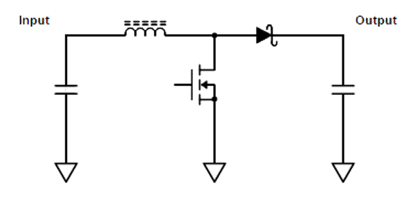
Figure 1: Simplified schematic of a boost converter
In this simplified schematic (Figure 1), constructed with capacitors, an inductor, a MOSFET, and a diode, the output is controlled through a closed feedback loop. The duty cycle, or the percentage of time the MOSFET is on, governs the output. The transfer function or ratio between the output voltage and the input voltage is
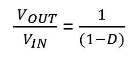
Where VOUT is the output voltage, VIN is the input voltage, and D is the duty cycle. A real boost converter would have a PWM controller chip, which is not shown in Figure 1.
Importance of Over-Voltage Protection
Over-voltage volatility can lead to accelerated aging, insulation breakdown, component failure, or even catastrophic damage to electrical equipment.
Equipment Protection
Over-voltage protection safeguards sensitive components, such as semiconductors, capacitors, and integrated circuits, from excessive voltage levels that could cause immediate or long-term damage. By limiting the voltage to safe levels, these protection measures ensure the longevity and reliability of these components.
System Stability
Over-voltage can disrupt the stability of the electrical system, leading to malfunctions, abnormal operation, or even design shutdown. Protection mechanisms mitigate over-voltage risks, maintaining system stability and ensuring an uninterrupted power supply.
Safety
In hazardous environments (Zone 2, Zone 1, and Zone 0), adequate protection against sparks and thermal ignition is imperative. This can be achieved through the use of products (Ex Components) that feature over-voltage limitation, thereby meeting the fundamental requirements for Intrinsic Safe Certification. Employing such components not only ensures compliance with safety regulations but also simplifies the certification process.
The Easiest Way for Safety
The easiest way to protect the load from overvoltage is to crowbar—that is, short out—the power source that caused the overvoltage condition. To ensure reliable protection, the overvoltage-protection circuit must be independent from the rest of the system’s circuits; it must have its own voltage reference and independent power source. The crowbar circuit usually requires a short trigger pulse.
Using this technique, but taking it to a higher level of protection, the ADOTT team created the B.PEx certified component.
BPEX - Intrinsically Safe Boost Converter Protection Module
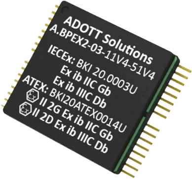
The A.BPEX module is designed to provide intrinsic safe protection for step-up (boost) DC-DC power supplies, which is commonly used in modern electronic devices. The unit limits the possible voltage supplied by the step-up converter in case of converter malfunction, thus making the design intrinsically safe against faults in the commercial DC-DC converter.
IEC and ATEX certified component: Zone 1 and Zone 2, Zone 21 and Zone 22
What Does the Boost Converter Protection Module Do?
The boost protection circuit includes two over-voltage protection (crowbar) circuits. These are guarding both the input (part A) and the output (part B) of the step-up (boost) switching mode power supply. If the step-up converter fails in such a way that the control loop become open, then the voltage at the output can increase to dangerous levels. To avoid this situation the output crowbar (part B) shorts the output rail to ground, so it clamps the output voltage, and also triggers the input crowbar (part B) to act the same, that blows the input fuse, thus separates the failed boost converter from the input power and protects the surrounding circuits.
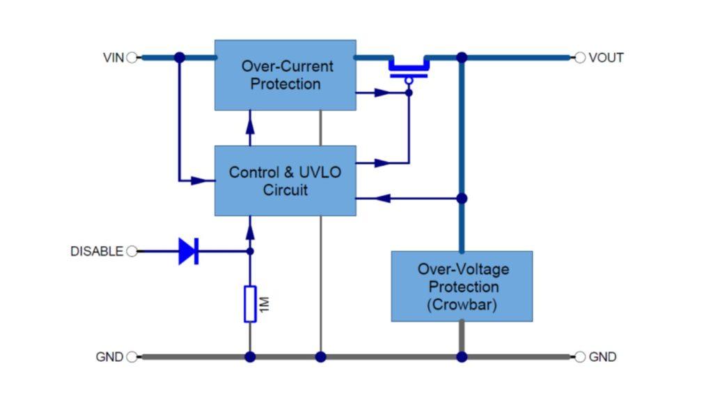
Figure 2: Block Diagram of B.PEx
How to use the Boost Converter Protection Module?
Check out the details on the product page and get in touch with our team to answer any further questions.
